SLURRY FRICTION HEAD LOSSES IN PIPELINES

SLURRY FRICTION HEAD LOSSES IN PIPELINES

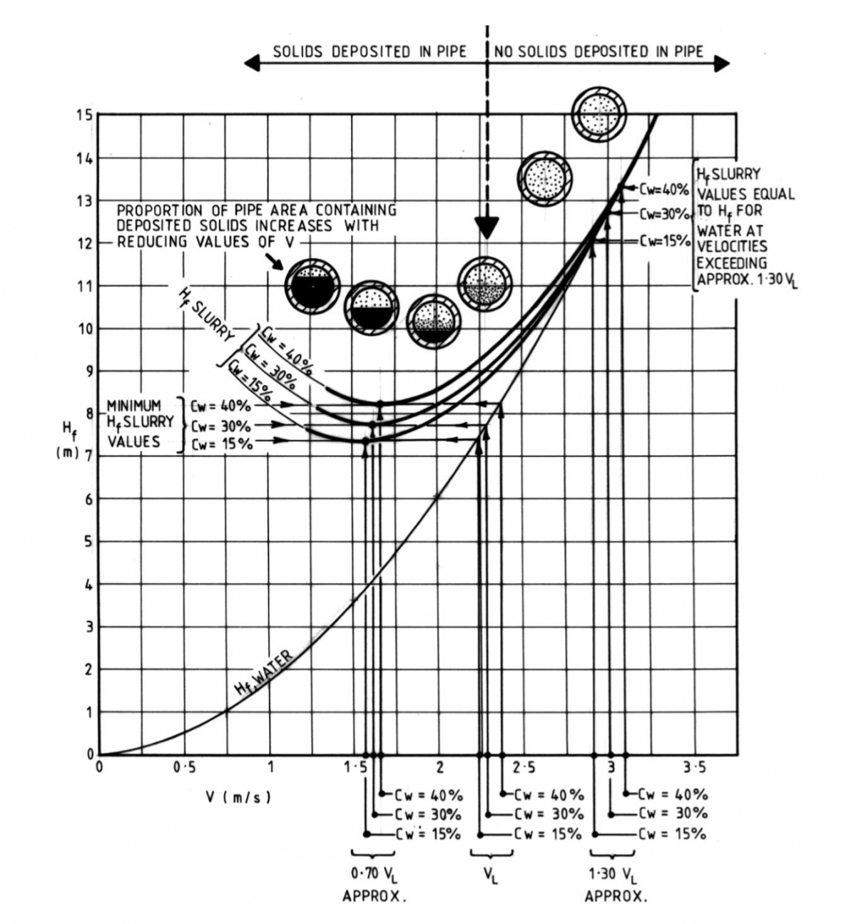
Despite the long history of successful slurry pumping operations covering a wide range of slurries, limited published data is available to estimate Hf accurately, for every possible duty. A high degree of accuracy is normally required only if Hf represents a high proportion of the Total Dynamic Head, H, for a proposed application so that large errors in estimating Hf would be reflected in correspondingly large errors in estimating H. Continue reading “SLURRY FRICTION HEAD LOSSES IN PIPELINES”

TOTAL DYNAMIC HEAD

TOTAL DYNAMIC HEAD

The main components of Total Dynamic Head are:

a) Total Discharge Head, and

b) Total Suction Head.

The equation is:

Total Dynamic Head = Total Discharge Head – Total Suction Head

Algebraically, H = (Hd) – (Hs) (m)

or, H = (Hgd + Hvd) – (Hgs + Hvs) (m)

The values Hvd and Hvs are always positive (+ve)

Hd is usually positive (+ve), (above pump centreline)

Hs may be positive (+ve), (above pump centreline) or negative (-ve), (below pump centreline).

When Hs is positive (+ve): H = (Hd) – (Hs) ie: H = Hd – Hs

When Hs is negative (-ve): H = (Hd) – (Hs) ie: H = Hd + Hs

a) Total Discharge Head, Hd

Basic Simple Formula: Hd = Zd + Hfd + Hve (m)

Zd may be positive (+ve) or negative (-ve)

If applicable, additional terms must be included in the formula to account for increased value of Hd, due to any contractions (for example, nozzle friction loss) and enlargements; friction loss in a flow-measuring device and exit into pressure-fed equipment, for example, a hydraulic cyclone.

b) Total Suction Head, Hs

Basic Simple Formula: (Hs) = (Zs) – Hi – Hfs (m)

(Hs) and (Zs) may each be positive, (+ve) or negative (-ve).

If applicable, additional or substitute terms must be included in the formula to account for increased or decreased values of Hs due to any contractions, enlargements, flow measuring device. These are as follows:

  1. liquid supply surface being under pressure, Hpr, or under vacuum, Hvac;
  2. ii) differential column head loss, Zc, and
  3. iii) substitution of effective mixture static suction head Zsm in lieu of Zs.

NOTE: Values of Hs are directly applicable in NPSHa calculations and in selection of shaft-sealing arrangements.

The term “Total Dynamic Head” correctly describes the driving force developed by a centrifugal pump, regardless of the Specific Gravity of the liquid or slurry pumped. The head (+ve) or (-ve) at any point in the system may be converted to pressure or vacuum, respectively, by the application of conversion formulae.

Total Dynamic Head, H, is the head which is required by a given system to maintain a given flow rate, Q, through the system.

H varies as the flow rate through the system, Q, varies. The relationship of H with Q is known as the System Resistance and may be expressed algebraically or graphically.

a) Total Dynamic Head: With Positive (+ve) Suction Head

Figure A4-1 illustrates a pump discharging a flow rate, Q, with discharge and suction gauge pressure heads, both relative to atmosphere and both corrected to pump centreline, measured at the pumps discharge flange and at the pump suction flange, respectively. All heads are expressed in metres of actual mixture being pumped.

The Total Dynamic Head, H, required to maintain flow rate Q through the system is the algebraic difference between the Total Discharge Head and the Total Suction Head.

H = Hd – (Hs)

= (Hgd + Hvd) – (Hgs + Hvs)

E:\MINECO\WEBSITE_MINECO\1_TOP LINE\2. Solutions\TDH-7.JPG

These velocities represent the actual values for average velocity at the pump discharge flange (Vd), and at the pump suction flange (Vs), respectively.

E:\MINECO\WEBSITE_MINECO\1_TOP LINE\2. Solutions\THD-1.JPG

FIGURE A4-1 TOTAL DYNAMIC HEAD WITH POSITIVE INTAKE HEAD

b) Total Dynamic Head: With Negative (-ve) Suction Head

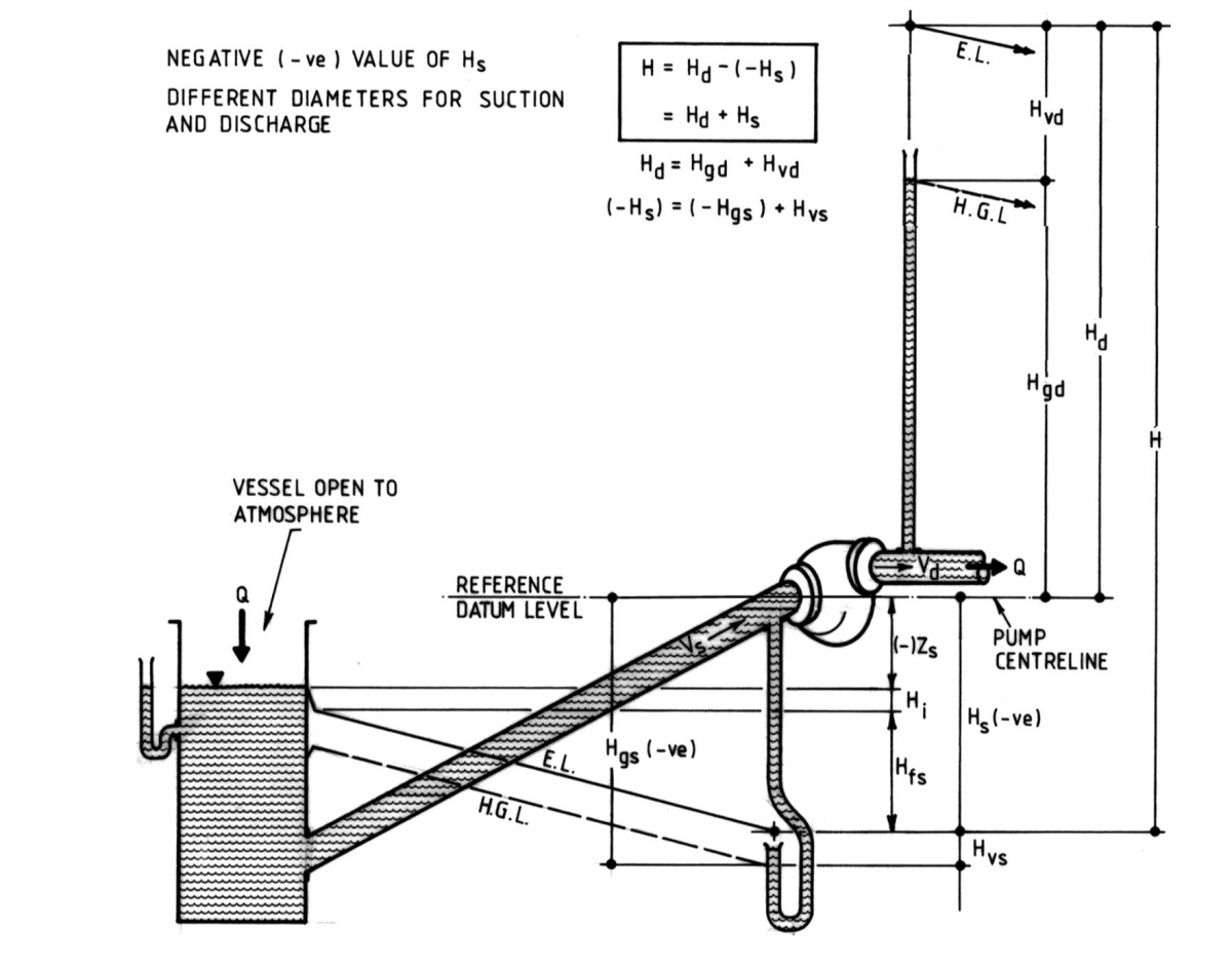
When Hs is negative (-ve) that is, a vacuum head is indicated by the gauge, as in Figure A4-2, the substitution of the negative value in the formula serves to positively increase the value of H with respect to Hd
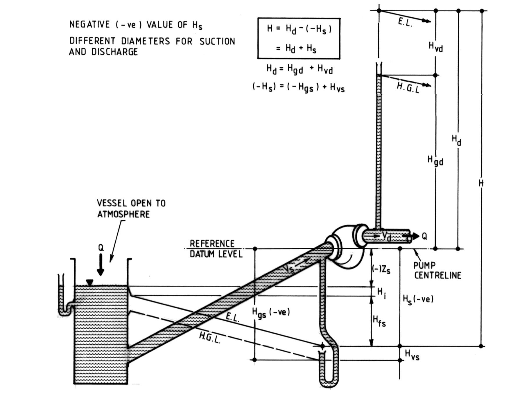
E:\MINECO\WEBSITE_MINECO\1_TOP LINE\2. Solutions\TDH-2.JPG

FIGURE A4-2 TOTAL DYNAMIC HEAD WITH NEGATIVE INTAKE HEAD

As H = (Hd) – (Hs) and as the suction and discharge pipes are often of different internal diameter, it is advisable to estimate values of Hd and Hs separately. The formulae used should be the Basic Simple Formulae, but amended where necessary to allow for any additional or substitute terms specific to the proposed duty as follows:

a) Total Discharge Head: Hd

Basic Simple Formula: Hd = (Zd) + Hfd + Hve

Typical possible additional terms are as follows:

i) Head Loss on conical enlargement (see Figure A4-4);

ii) Head Loss on contraction (see Figure A4-4);

iii) Head Loss on Exit into Pressure-Fed Equipment (refer to Head Loss at Exit into Pressure-Fed Equipment).

b) Total Discharge Head: Hs

Basic Simple Formula: Hs = (Zs) + Hi + Hfs

Typical possible additional terms are as follows:

i) Head GAIN in supply from Pressure Vessel, Hpr;

ii) Head Loss in supply from Vacuum Vessel, Hvac

iii) Head Loss on Differential Column (applicable in dredge applications, Zc – refer to Differential Column Head Loss)

a) Pipeline Friction Head Loss, Hf

The friction head loss in a given pipeline is estimated for the Total Equivalent Length of Pipe, L(m), which is the sum of the Total Actual Length of Pipe, La(m) and the Aggregate of Equivalent Lengths for all valves, bends and like fittings, Lf(m) (see Figure A4-3) contributing to friction head loss in the pipeline.
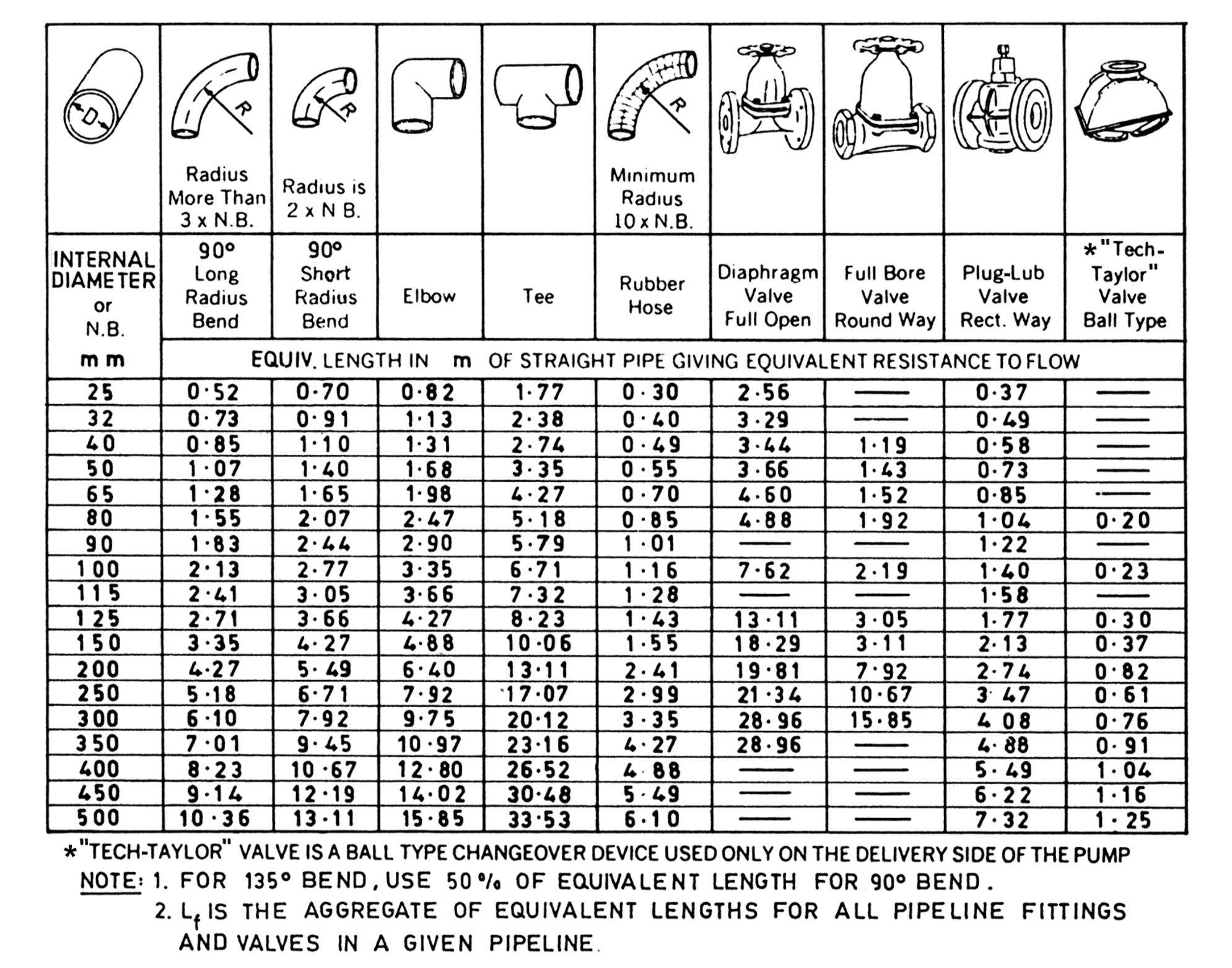
E:\MINECO\WEBSITE_MINECO\1_TOP LINE\2. Solutions\TDH-3.JPG

FIGURE A4-3 EQUIVALENT LENGTHS OF PIPE FITTINGS AND VALVES

Generally L = La + Lf.

Specifically:

i) For Suction Side: Ls = Las + Lfs (Friction Head Loss = Hfs)

ii) For Discharge Side: Ld = Lad + Lfd (Friction Head Loss = Hfd)

Values of Hfs and Hfd should be estimated separately, for example, during the preparation of the respective separate sets of calculations leading to the estimates of Hs and Hd. By separately estimating Hs, its value is readily available for use in NPSHa CALCULATIONS, (refer to APPENDIX 6 – NET POSITIVE SUCTION HEAD (NPSH)), and in the selection of Shaft-Sealing arrangements (refer to Shaft Sealing).

b) Inlet Head Loss, Hi: Exit Velocity Head Loss, Hve

Separate provision is always made in the standard formulae for the terms:

i) Hi, the Inlet Head Loss (Suction side only), and

ii) Hve, the Exit Velocity Head Loss (Discharge side only).

That is, the terms Hi and Hve are included in the standard formulae for Hs and Hd respectively.

c) Head Losses due to Contractions and Enlargements

These additional head losses are calculated by use of the formulae provided in Figure A4-4. As no separate provisions are made in the standard Hs and Hd formulae for individual symbols or terms anticipating these friction head losses, any such estimated head losses, if applicable, should properly be added to the values calculated for Hfs or Hfd respectively.

Friction losses in jet nozzles (Hn) may be treated as for conical contractions unless more reliable head loss data is available.
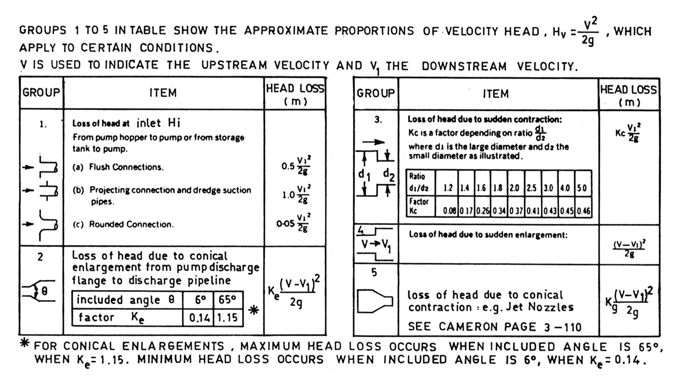
E:\MINECO\WEBSITE_MINECO\1_TOP LINE\2. Solutions\TDH-4.JPG

FIGURE A4-4 HEAD LOSSES AT INLET, CONTRACTION AND ENLARGEMENT

d) Sundry Additional Causes of Effects on Hfs or Hfd

The calculated values for Hfs and Hfd must be corrected to allow for permanent friction head losses when any in-line restrictions, such as flowmeasuring devices, are intended to be installed (for example, quarter-circle orifice plates).

e) Differential Column Head Loss

Figure A4-5 depicts a mixture of Specific Gravity, Sm, flowing upwards and drawn from a supply of settled solids and overlying liquid, Sl. As the liquid of the same vertical height, Zl. The resulting effective static head loss is known as the differential Column Head loss, Zc:

E:\MINECO\WEBSITE_MINECO\1_TOP LINE\2. Solutions\TDH-5.JPG

Sm is greater than Sl, the vertical height Zl, of mixture in the submerged portion of the suction pipe is not completely balanced by the surrounding

Where this condition exists, Zc must be included as an additional head loss in the pipe system. This would effect both total head and NPSHa (refer to APPENDIX 6 – NET POSITIVE SUCTION HEAD (NPSH)).

E:\MINECO\WEBSITE_MINECO\1_TOP LINE\2. Solutions\TDH-6.JPG

FIGURE A4-5 DIFFERENTIAL COLUMN HEAD LOSS


OPTIMISE PLANT PERFORMANCE THROUGH REMOTE, CONTINUOS MONITORING

Digitalisation opens the door to enhanced plant performance

Depletion of mineral deposits creates a profitability and productivity challenge, forcing industry leaders to develop innovative solutions.

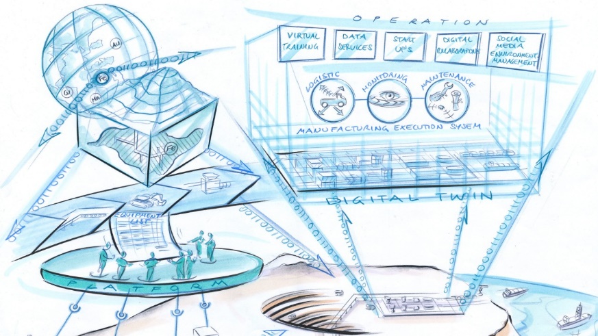
Digitalization itself cannot mine the ores, but digging into data and using new technologies is the opportunity to mine smarter and increase productivity.

E:\MINECO\WEBSITE_MINECO\6_ENGINEERING SERVICES_02 pages\Process Optimisation\161213-digitalmine.jpg

Take advantage of digitalisation and optimise your mine performance

We are at the brink of a new standard for enhancing productivity in mining operations, and its arrival comes not a second too soon.

With the world’s increasing hunger for minerals alongside resource scarcity, you must dig deeper and in more remote areas to meet this need.

Optimising your process has never been more crucial to the productivity and bottom line of your mining operation.

E:\MINECO\WEBSITE_MINECO\6_ENGINEERING SERVICES_02 pages\Process Optimisation\Capture10.JPG

The interconnectivity of technologies enabled by Internet as well as data collection and analysis are rapidly developing across the world and across industries. Born from a necessity to improve the mining processes, these technological tools are now ready to benefit the mining industry as well. As of yet, an estimation of only 5% of mining operations make use of the IoT, as well as only a 1% usage of all data collected in the mining industry. Our understanding of for example the resource base then comes from only applying 1% of the knowledge available to us. Imagine the strides we could make if we made use of all the valuable data.E:\MINECO\WEBSITE_MINECO\6_ENGINEERING SERVICES_02 pages\Process Optimisation\Capture2.JPG

How Internet of Things can optimise your productivity 

The interconnectivity can be used to affect three factors in your mining operation: process optimisation (quality and throughput), maintenance strategies and utility consumption. Understanding the advanced sensing and the data analytics allows plant managers to make good decisions about balancing operations. Equipment may need to be pushed harder in order to meet quotas, but can also be slowed down if necessary.

E:\MINECO\WEBSITE_MINECO\6_ENGINEERING SERVICES_02 pages\Process Optimisation\Capture3.JPG

As an example, you might have a crusher where the sensor data indicates that the mantle has been worn down to a certain level. The system could then adjust the opening and operation of the crusher to maintain the desired particle size, despite the machine being somewhat worn.

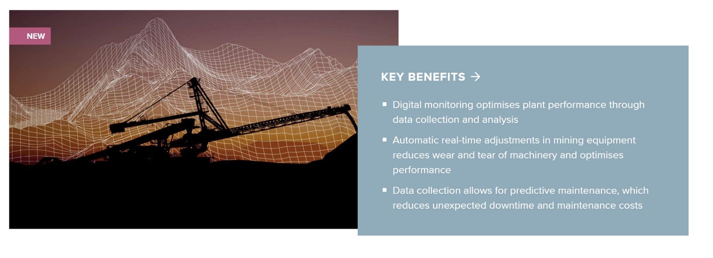
Simply put, a process control system can measure and assess a large number of parameters and their interdependencies within mere seconds, far superior to anything that could be done manually. Adjustments and optimisations done in real time allows for the increase in production, lower energy consumption, reduced wear and tear to name a few. The system also allows for predictive maintenance, meaning you can avoid unexpected downtime and maintenance costs. If implemented properly, the whole mining operation can be optimised creating a big potential for you and your bottom line.

Data – the resource with the highest potential? 

If it does not already, proper data analysis will play a crucial role for your mining operation and its productivity in the future. With increasing resource demands, as well as scarcity of minerals, players in the mining industry are forced to adopt new solutions, if they wish to survive and continue to meet demands. Digital innovations, providing knowledge about everything from the resource base to real-time performance of equipment, will increase your productivity.

An example of how to reap the benefits of data analysis is the PlantLine™ Service Agreement, which is a partnership between you as our customer and us. With the agreement, plant performance is proactively optimised through remote, continuous monitoring and adjustments to various parameters on the equipment.

E:\MINECO\WEBSITE_MINECO\6_ENGINEERING SERVICES_02 pages\Process Optimisation\Capture12.JPG

PlantLine is a combination of online support, on site support and training of personnel. Issues can be resolved quickly and for the most part remotely. If a solution requires on site support, the problem can almost always be diagnosed online, meaning shorter wait times for a person to show up with the right equipment.

At FLSmidth, we work hard to lead this technological innovation and constantly seek new ways to enhance your productivity through digitalisation of equipment across the flow-sheet. Together, we can create the most possible value from digitalisation and your mining operations.

E:\MINECO\WEBSITE_MINECO\6_ENGINEERING SERVICES_02 pages\Upgrade Process Automation\Capture8.JPG

Global Leading Manufacture:                 E:\MINECO\WEBSITE_MINECO\About us\partner logo\FLSmidth -logo.PNG


Improving flotation efficiency, Innovation in flotation

You need to make sure that your design criteria meet the specific demands of your mine. Yet, bottlenecks still occur, and undersized dewatering circuits are extremely unforgiving. So how can you make a flotation device more efficient without making it consume more energy? Our flotation team was pretty sure that they could improve the energy efficiency of flotation by rethinking the rotor/stator technology. It just required a change in the hydrodynamics of the flotation system.E:\MINECO\WEBSITE_MINECO\6_ENGINEERING SERVICES_02 pages\Upgrade Process Automation\Capture1.JPG

Reduce energy consumption, improve performance 

The answer they came up with was the nextSTEP™ rotor/stator. But the longer story about how that technology was developed shows how cooperation across industries and academia can help save energy and improve productivity in your mine.

A step change in both metallurgical performance and energy efficiency

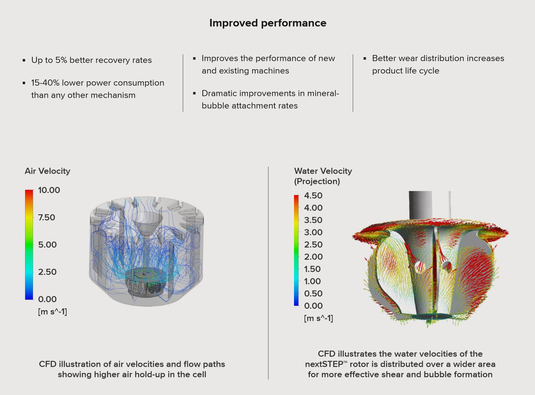
The nextSTEP™ Rotor is designed to produce ideal flow streams. It also produces strong enough turbulence to enhance bubble-particle attachment. This improves recovery rates and concentration grades while lowering energy requirements.

Improved performance

FLSmidth is the world’s largest supplier of flotation equipment offering lower energy consumption, improved recovery and increased operational efficiency.

For the initial technology developmental phase, we teamed up with aerospace researchers, surface chemistry researchers and the Center for Advanced Separation Technologies at Virginia Tech. The combination of mining industry academics and experts from the aerospace industry allowed the team to come up with an innovative design concept for the rotor/stator.

Smaller bubbles have better attachment properties than large ones. But if you increase the rate to improve throughput, the flotation cells produce larger, not smaller bubbles. So it’s really not a straightforward proposition.

The aim was to design a machine that enabled an increase in the the air volume and a reduction in the bubble size at the same time, while optimising the energy dissipation rate.

E:\MINECO\WEBSITE_MINECO\6_ENGINEERING SERVICES_02 pages\Improving Flotation Effeciency\Capture20.JPG

Saving energy and improving performance

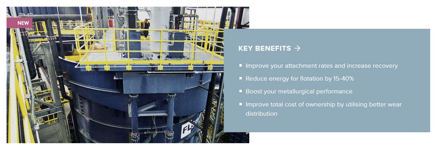
The target was to create a new ultra low-energy flotation system. The team succeeded to the extent that the nextSTEP™ rotor/stator reduces your power requirements by 15-40 percent and has the lowest operating power of any forced-air flotation mechanism on the market.

E:\MINECO\WEBSITE_MINECO\6_ENGINEERING SERVICES_02 pages\Upgrade Process Automation\Capture7.JPG

To create an environment for the bubbles and particles to make contact with the least amount of power possible, the vane of the rotor was elongated and slots were cut in the stator to optimise the geometry of the rotor/stator assembly.

The design also improves your performance. The new rotor produces ideal flow streams and an energy dissipation rate that enhances the bubble-particle attachment. The patented rotor/stator makes energy dissipation more uniform which results in a higher probability of bubble to particle contact during the flotation process. This dramatically improves your attachment rates.

Froth Recovery Upgrade Package

Improve metallurgical performance with advanced froth phase control

Enjoy superior froth-level control and metallurgical performance, with the FLSmidth Froth Recovery Package. Take your flotation cell to the next level with actuators, level sensors and radial froth crowders designed to provide improved recovery and grade.

E:\MINECO\WEBSITE_MINECO\6_ENGINEERING SERVICES_02 pages\Upgrade Process Automation\Capture10.JPG

Get the most out of froth recovery with our Froth Recovery Package

Often, before you can put your valuable ore to good use for your business, you need to separate it out from the waste material. And in many cases, the answer is froth flotation. However, froth flotation is not an exact science, and small-yet-numerous particles of valuable ore may be getting thrown out with the tails. These can add up, accounting for a significant loss in potential revenue. Our Froth Recovery Package offers a solution that not only improves froth recovery, but also saves overall costs.

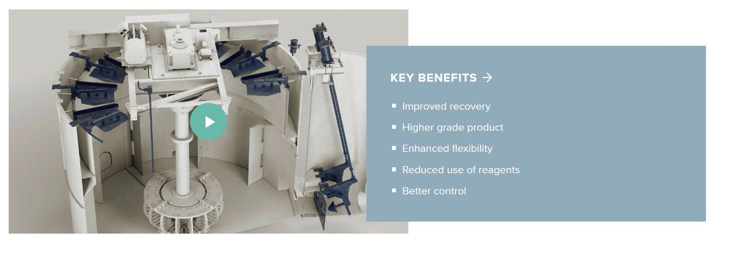
The Froth Recovery Package enables you to better control the froth phase, which in turn improves the performance of the flotation cell. The addition of the radial froth crowders adds a new dimension to the control strategy. It allows you to shift the grade recovery curve by allowing either deeper froth or faster froth removal.

Proven technology from experienced Froth Recovery Package manufacturer

E:\MINECO\WEBSITE_MINECO\6_ENGINEERING SERVICES_02 pages\Upgrade Process Automation\Capture9.JPG

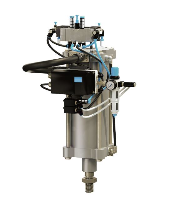
Actuators

Actuators control the position of the dart valve inside the flotation cells

E:\MINECO\WEBSITE_MINECO\6_ENGINEERING SERVICES_02 pages\Upgrade Process Automation\Capture11.JPG

Level sensor

Featuring a new robust design with no moving parts that accurately senses slurry level, the Level Sensor is one of the most accurate on the market

E:\MINECO\WEBSITE_MINECO\6_ENGINEERING SERVICES_02 pages\Upgrade Process Automation\Capture13.JPG

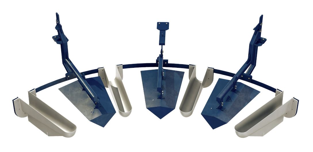
Radial Froth Crowders

Designed for greater flexibility and control, radial froth crowders reduce top-of-froth surface area and increase froth movement to the nearest radial launder

Global Leading Manufacture:            E:\MINECO\WEBSITE_MINECO\About us\partner logo\FLSmidth -logo.PNG

Measuring everything that matters

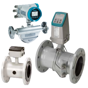
Siemens Process Instrumentation offers you innovative, single-source measurement solutions to increase plant efficiency and enhance product quality.E:\MINECO\WEBSITE_MINECO\5_POWER INDUSTRY_08 pages\8. Control & Instrument_01age\Capture13.JPG

Siemens instruments are also designed for seamless interplay with the larger world of industrial automation and control systems – enabling greater process transparency Benefit from the competence of Siemens: a full automation vendor operating around the globe, with service available 24 hours a day, 365 days a year.

E:\MINECO\WEBSITE_MINECO\5_POWER INDUSTRY_08 pages\8. Control & Instrument_01age\EMGT31-1030x685.jpg

INSTRUMENT PRODUCT RANGE:

E:\MINECO\WEBSITE_MINECO\5_POWER INDUSTRY_08 pages\8. Control & Instrument_01age\5c8dbea7e9eba.jpg

Pressure measurement

E:\MINECO\WEBSITE_MINECO\5_POWER INDUSTRY_08 pages\8. Control & Instrument_01age\5c8dbf44dd343.jpg

Temp. measurement

E:\MINECO\WEBSITE_MINECO\5_POWER INDUSTRY_08 pages\8. Control & Instrument_01age\5c8dbfc26c7f3.jpg

Flow measurement

E:\MINECO\WEBSITE_MINECO\5_POWER INDUSTRY_08 pages\8. Control & Instrument_01age\5c8dc01f26e32.jpg

Level measurement

E:\MINECO\WEBSITE_MINECO\5_POWER INDUSTRY_08 pages\8. Control & Instrument_01age\5c8dc152a5bb2.jpg

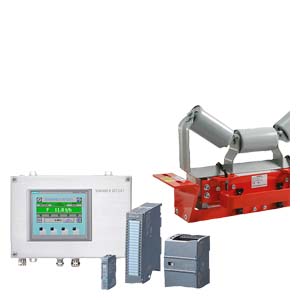
Weighing technology

E:\MINECO\WEBSITE_MINECO\5_POWER INDUSTRY_08 pages\8. Control & Instrument_01age\5c8dc1bc36880.jpg

Process controllers

THE LEGENDARY UNIVERSAL PLC

SIMATIC S7-300 – Proven multiple times!

The SIMATIC S7-300 is used in many applications worldwide and has been proven successful millions of times. The SIMATIC S7-300 universal Controllers saves on installation space and features a modular design. A wide range of modules can be used to expand the system centrally or to create decentralized structures according to the task at hand, and facilitates a cost-effective stock of spare parts.

The S7-300 is the individual solution for fast process and automation tasks that contain additional data processing tasks. It is high-performance, fast, versatile and future-proof. For engineering either STEP 7 V5.6/STEP 7 Professional 2017 or STEP 7 Professional in the TIA Portal can be used.

E:\MINECO\WEBSITE_MINECO\5_POWER INDUSTRY_08 pages\8. Control & Instrument_01age\6940-tia-portal-advanced-controller-151105-01-cmyk.jpg

E:\MINECO\WEBSITE_MINECO\5_POWER INDUSTRY_08 pages\8. Control & Instrument_01age\Capture5.JPG

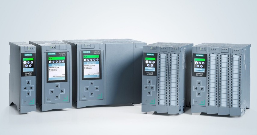
SIMATIC S7-1500 – probably the fastest controller worldwide

Using the SIMATIC S7-1500 controller gives you top performance and built-in viability into the future. You can turn the most sophisticated machine designs into reality thanks to the modular structure of the controller, which provides reliable assistance as you work your way through the digital transformation.

The central processing units (CPU) are the heart of the SIMATIC S7-1500. They execute the user program and network the controller with other automation components. Thanks to numerous innovations, the CPUs of the SIMATIC S7-1500 deliver the ultimate plus in productivity and efficiency.

E:\MINECO\WEBSITE_MINECO\5_POWER INDUSTRY_08 pages\8. Control & Instrument_01age\Capture2.JPG

E:\MINECO\WEBSITE_MINECO\5_POWER INDUSTRY_08 pages\8. Control & Instrument_01age\Capture4.JPG

Global Leading Manufacturers :          E:\MINECO\WEBSITE_MINECO\5_POWER INDUSTRY_08 pages\Electric Equipment-01page\Capture3.JPG

ELECTRIC MOTORS

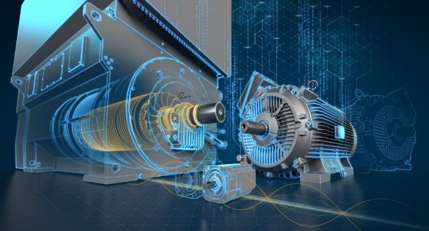
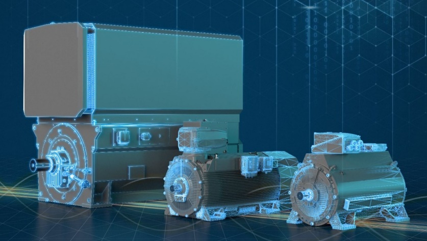
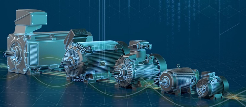
Electric motors are synonymous with quality, innovation and the highest efficiency. We cover the complete range of industrial motors – synchronous as well as asynchronous: from standard electric motors through servomotors for motion control applications up to high voltage and DC motors.

E:\MINECO\WEBSITE_MINECO\5_POWER INDUSTRY_08 pages\Electric Equipment-01page\Capture0.JPG

High Voltage Motors – for every demand

Power range from 150 kW up to 100 MW and more, speeds from 7 to 15,900 rpm, and torques up to 2,460 kNm and conformity with IEC and NEMA standards. Options include several cooling systems and all common explosion protection types. In addition, degrees of protection up to IP66 and special paint systems are available for use in aggressive atmospheres and under extreme conditions.

E:\MINECO\WEBSITE_MINECO\5_POWER INDUSTRY_08 pages\Electric Equipment-01page\High voltage mottor.JPG

Low-Voltage Motors for the Industry

Power range of motors from 0.09 KW up to 5 MW. They conform to IEC and NEMA standards and they are highly efficient. The motors can be used either direct on line or for converter operation in combination with the wide range of SINAMICS converters.

E:\MINECO\WEBSITE_MINECO\5_POWER INDUSTRY_08 pages\Electric Equipment-01page\low voltage motor.JPG

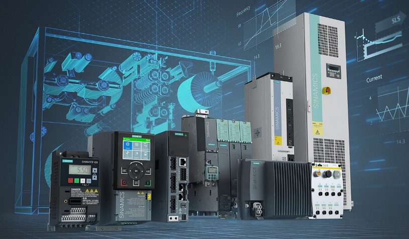
FREQUENCY CONVERTER

SINAMICS Standard Performance Frequency Converters are perfectly adapted to basic to mid-level control dynamics requirements. The converters are based on the same platform as all other members of this innovative drives family. Users benefit from a standardized and user-friendly operating concept without requiring additional engineering tools.

E:\MINECO\WEBSITE_MINECO\5_POWER INDUSTRY_08 pages\Electric Equipment-01page\Capture6.JPG

Application: Pumps, fans, compressors, conveyor belts, mixers, mills or extruders

GAS INSULATED MEDIUM VOLTAGE SWITCHGEAR

8DJH switchgear is a factory-assembled, type-tested, 3-pole metal-enclosed single-busbar switchgear for indoor installation. 8DJH switchgear is used in public and industrial energy systems of the secondary distribution level.

Technical data:

• Up to 17.5 kV, 25 kA, 630 A busbar, 630 A feeder
• Up to 24 kV, 20 kA, 630 A busbar, 630 A feeder
• Metal-enclosed
• Gas-insulated
• Hermetically enclosed
• Factory-assembled, routine-tested according IEC 62271-200
• Type-tested according IEC 62271-200

Customer’s Benefit:

• Security of Operation, Reliability
• Maintenance-free Design
• Personal Safety
• Environmental Independence
• Compactness
• Economy, Ecology

E:\MINECO\WEBSITE_MINECO\5_POWER INDUSTRY_08 pages\Electric Equipment-01page\Capture8.JPG

Global Leading Manufacturers:        E:\MINECO\WEBSITE_MINECO\5_POWER INDUSTRY_08 pages\Electric Equipment-01page\Capture3.JPG

In-Plant BELT CONVEYOR

Belt Conveyor offers safe mechanical conveying of materials

Our In-Plant Belt Conveyor solution is an easy to operate and maintain mechanical conveying system. Designed with safety at top of mind, easily accessible maintenance parts and a dynamic rock box deliver trouble-free mechanical conveying of materials.

E:\MINECO\WEBSITE_MINECO\4_FLOTATION REAGENTS_03 pages\BASF pictures\Capture3.JPG

Ensure safe mechanical conveying with our In-Plant Belt Conveyors

Our In-Plant Belt Conveyor offers safe mechanical conveying for the cement industry and is built to handle sticky and highly-abrasive materials. We provide a solution that minimises blockages and liner wear while extending the life of the belt and other major components.

E:\MINECO\WEBSITE_MINECO\5_POWER INDUSTRY_08 pages\6. Converyor Belts-01page\Capture1.JPG

Airlift™ VERTICAL PNEUMATIC CONVEYING OF FINE-GRAINED AND POWDERY DRY BULK MATERIALS

Sometimes, the only way to go is up. Mechanical conveying systems can get you there, but what about the dust? The maintenance? The Airlift™ vertical pneumatic conveying system is a clean, safe and low-maintenance option that can transport material to heights of more than 100 m at rates of up to 1000 t/h.

E:\MINECO\WEBSITE_MINECO\5_POWER INDUSTRY_08 pages\6. Converyor Belts-01page\Capture4.JPG

Tailored to your application

• The cylindrical part of the Airlift™ housing is available in different stepless heights depending on the bulk material to be conveyed, the desired conveying capacity and lifting height.

• The Airlift™ can be equipped with fluidisation fabric for bulk material temperatures of up to 300°C and wear-resistant lining for highly abrasive materials.

• The bulk material can be fed into the upper cylindrical part of the elevator housing vertically or from the side.

The Airlift™ System is suitable for materials that can be fluidized by aeration without segregation, such as:

• Cement, Raw meal, Alumina, Copper concentrate

• Fly ash, Copper flue dust, Fluid coke, Catalyst

• Limestone, Sand, Slag dust

The minimum capacity is approximately 1 t/h on a continuous basis, while capacities of 1000 t/h and lifting heights of up to 100 m can be achieved.

Airlift™ systems are custom-engineered for each application – the limits of capacities and lifting heights are a matter of design. And with more than 300 references around the world, we have the experience to design to your requirements.

Airslide® GRAVITY CONVEYOR

Low-maintenance, low-energy fluidized conveying of dry bulk materials

FLSmidth’s Airslide fluidized conveying systems harness the power of gravity, giving you a system that is low maintenance, high efficiency and high performance. Through effective fluidization technology, throughputs of more than 2000 m3/h are possible with very low energy consumption.

E:\MINECO\WEBSITE_MINECO\5_POWER INDUSTRY_08 pages\6. Converyor Belts-01page\Capture5.JPG

Typical Airslide Conveyor Applications include:

• Distribution from bucket elevators to storage silos

• Gathering under baghouses / precipitators

• Feed to process

• Feed to other conveyors

• Loadout from bulk silos to trucks, railcars or barges

• In-plant conveying

• Storage silo / bin withdrawal

DRAG CHAIN CONVEYOR

Our Drag Chain Conveyors reliably transport bulk materials with efficiency

Our Drag Chain Conveyors offer quick and efficient enclosed transport of powdery, floccose, grained and coagulative bulk materials. They can be designed as watertight, dust-proof, pressure-tight and explosion-proof in accordance with current ATEX norms.

E:\MINECO\WEBSITE_MINECO\5_POWER INDUSTRY_08 pages\6. Converyor Belts-01page\Capture6.JPG

Bulk materials able to be transported in the Drag Chain Conveyor includes:

• coal, sorted domestic waste, sewage sludge

• filter dust, fly ash, wood chips and wood dust

• refuse-derived fuel (RDF), solid recovered fuel (SRF)

• cement, clinker, limestone, biomass, alternative fuels and many others.


Global Leading Manufacturers:         E:\MINECO\WEBSITE_MINECO\About us\partner logo\FLSmidth -logo.PNG

POWER TRANSMISSION EQUIPMENTS

E:\MINECO\WEBSITE_MINECO\5_POWER INDUSTRY_08 pages\Tranmission equipment-01page\Capture6.JPG

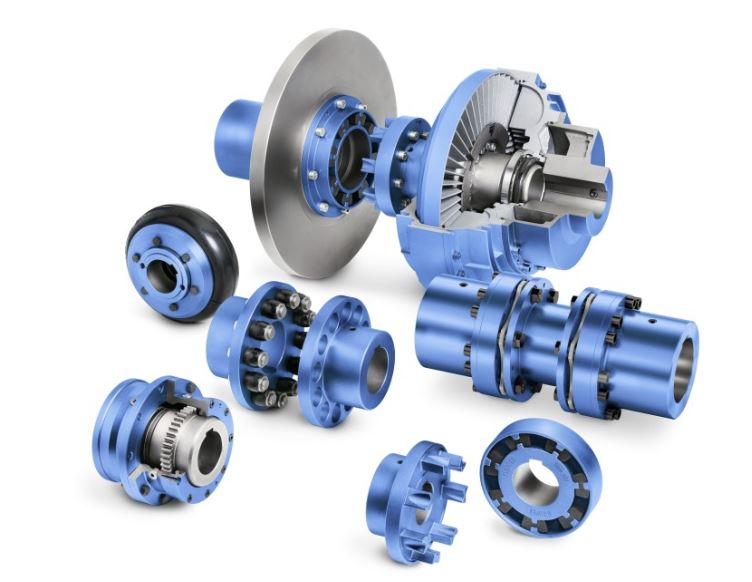
Power Transmission products refers to various components that allow for internal parts to operate properly in machinery. These items typically include: belts, chains, couplings, pulleys, sprockets, bushings, hubs, bearings, linear actuators, slide rails, bevel gears, worm gears, and various other components.

COUPLING

A shaft coupling is used to join two shafts together and to ensure that the two shafts rotate together

Rigid couplings connect well-aligned shafts, while flexible shaft couplings are used to cancel out the misalignment between two shafts.

These components can also be used to absorb or reduce shock and vibrations. Some of the many different kinds of couplings include bellows couplings, flywheel couplings, jaw couplings, universal joints, fluid couplings, and torque limiters. Couplings are commonly used in power transmissions, generators, wheels, pumps, and turbines.

E:\MINECO\WEBSITE_MINECO\5_POWER INDUSTRY_08 pages\5. Tranmission equipment-01page\Capture10.JPG

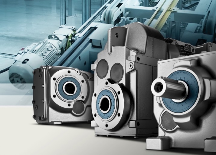
GEARMOTORS

Essentially, a gearmotor is a pairing of gear reducer and ac or dc electrical motor. The gear and the motors are combined into one unit.

A gearmotor delivers high torque at low horsepower or low speed. The speed specifications for these motors are normal speed and stall-speed torque. These motors use gears, typically assembled as a gearbox, to reduce speed, which makes more torque available.

Gearmotors are most often used in applications that need a lot of force to move heavy objects.

E:\MINECO\WEBSITE_MINECO\5_POWER INDUSTRY_08 pages\Tranmission equipment-01page\Siemens-Gearmotors-SIMOGEAR-efficiency-example-1024x739.jpg

SPEED REDUCERS

Speed reducers are used to redirect the output of a high-speed motor to another component at a lower speed.

Gears within the speed reducer provide the mechanism for reducing the output speed of the motor.

The size ratio of the input gear to the output gear is directly related to the speed reduction, so different sized gears can be used to achieve different speeds.

Speed reducers are know by many names and come in a variety of configurations. These include cyclo reducers, gear reducers, gearboxes, right angle gear boxes, and planetary gearboxes.

E:\MINECO\WEBSITE_MINECO\5_POWER INDUSTRY_08 pages\5. Tranmission equipment-01page\Capture.JPG
Leading Manufactures: E:\MINECO\WEBSITE_MINECO\5_POWER INDUSTRY_08 pages\Electric Equipment-01page\Capture3.JPG


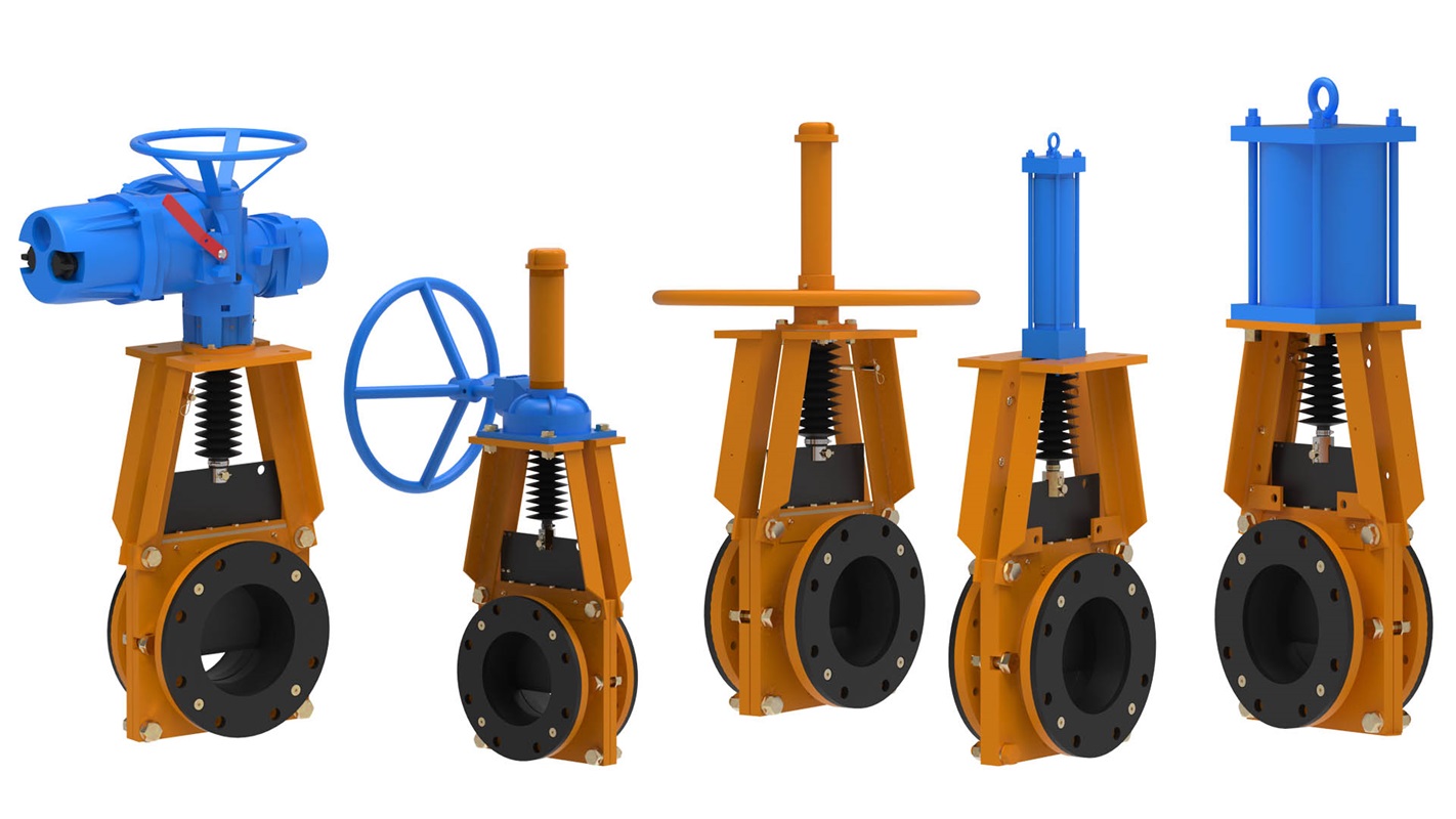
The Technequip™ Knife Gate Valve is a true bi-directional slurry knife gate valve. Its massive rubber sleeves were designed to seal and withstand the harsh abrasive duty inherent in mining and milling facilities.E:\MINECO\WEBSITE_MINECO\5_POWER INDUSTRY_08 pages\Knife gate valves_01page\Knife gate valve pictures\Krebs TG knife gate slurry valves for slurry handling.jpgThe Technequip™ Knife Gate Valve Standard Features:

• Fluorocarbon coated 316L stainless steel gate

• Zinc-Nickel Plated Hardware

• Epoxy Paint

• Bi-Directional Operation

• No Packing to bind the gate

• Low Durometer Seats for maximum erosion protection

• ANSI B16.5 Class 150 fl ange bolt pattern

• All air cylinder actuated valves are supplied with an internal ring magnet for position indication

• Interchangeable with the Clarkson KGA™ J-Ring model knife gate valve

• Cylinder mounted reed / proximity switches (non-contacting)

• Seats available in pure gum rubber / neoprene / chlorobutyl / E.P.D.M.

• Solenoid valves with manual override and power indication LED

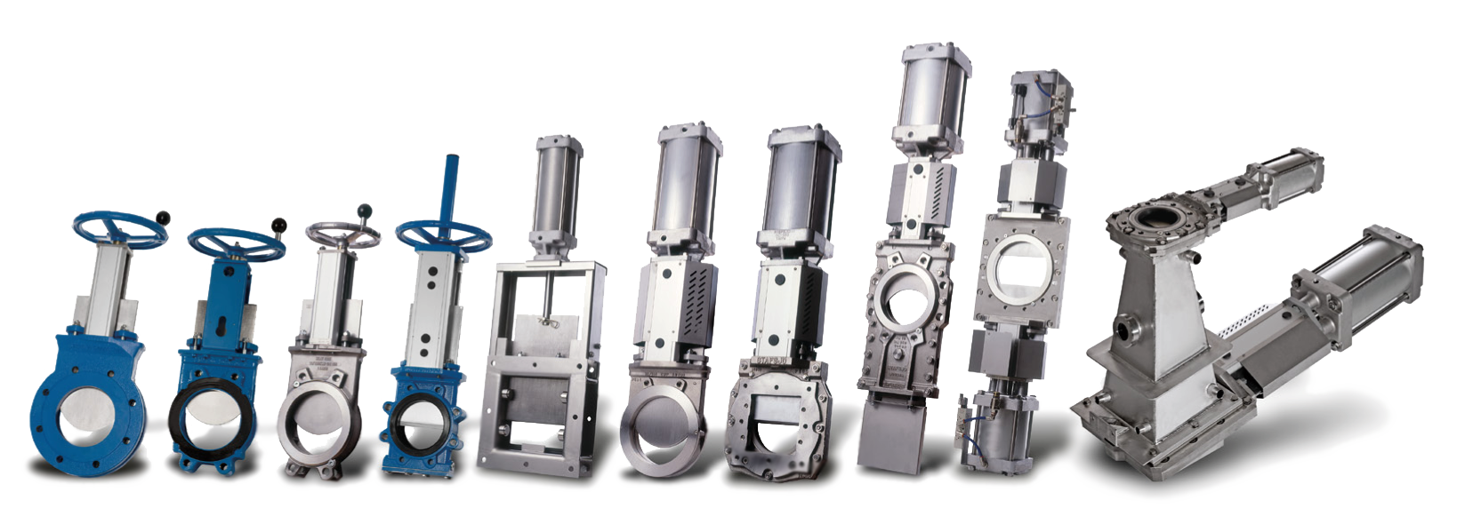
Product Range:E:\MINECO\WEBSITE_MINECO\5_POWER INDUSTRY_08 pages\Knife gate valves_01page\Knife gate valve pictures\Stafjoe5.pngE:\MINECO\WEBSITE_MINECO\5_POWER INDUSTRY_08 pages\Knife gate valves_01page\Capture1.JPG

Leading Manufacturer:

E:\MINECO\WEBSITE_MINECO\About us\partner logo\FLSmidth -logo.PNG