SERIES PUMPING
Many pumping duties require slurries to be transported over long distances and/or against very high static discharge heads, for example, against total heads well in excess of heads which can be developed by a single centrifugal slurry pump.
Typical examples include many requirements for the pumping of concentrates, tailings, power station ash and underground fill. The high flow rates required are commonly beyond the capacities of available positive displacement pumps (PDP’s). In addition, the overall % efficiency, that is:

of large centrifugal slurry pump installations competes with PDP’s essentially due to:
a) the high efficiency of large centrifugal slurry pumps, and
b) the higher efficiencies of the lower-ratio drives between electric motors and the centrifugal pumps. These pump applications which require a high Total Head can be handled by series pumping, either as:
i. multi-stage pump units, or
ii. separate pumps spaced at intervals along the pipeline route.
Figure A7-1 represents a single centrifugal pump operating at duty point “A”, and at pump speed, n1. For the required flow rate Q1, the pump can develop a head H1 at an efficiency, em1, and at a power consumed of P1. That is, the Duty Point “A” is Q1/H1.
NOTE: The hydraulic grade line (HGL) indicates the actual static head available at any point along the length of the pipeline.

FIGURE A7-1 SINGLE PUMP
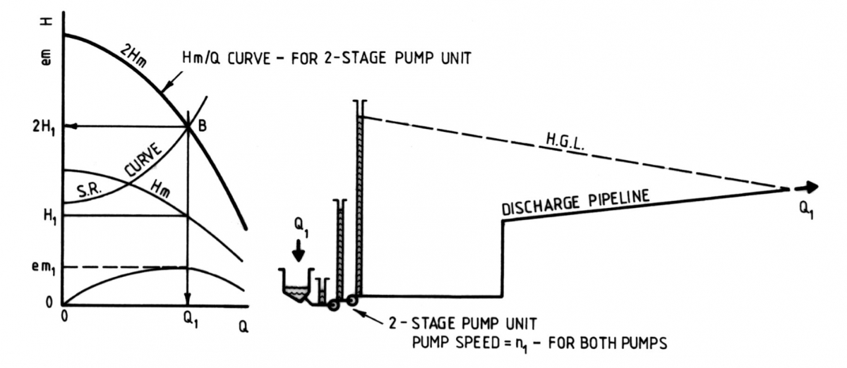
Figure A7-2 represents two identical pumps, arranged in series so that the entire flow discharged from the 1st Stage pump is piped, under pressure through a short length of piping, directly to the suction flange of the 2nd Stage pump and finally from the discharge of the 2nd Stage pump into the discharge pipeline. If both pumps are operated at the same speed, n1 and as both are handling the same required flow rate, Q1, each will develop the same Head, H1, at the same efficiency, em1, and consume the same power, P1.
The total head developed by the 2-stage pump unit combination = 2 x H1, that is,
Duty Point “B” is Q1/2H1
Accordingly, both pumps will be operating under the same conditions, except that the Suction Head and the Discharge Head of the 2nd Stage Pump will both be higher by the value of the Discharge Head of the 1st Stage Pump (less small losses in the interstage piping).

FIGURE A7-2 SINGLE PUMP
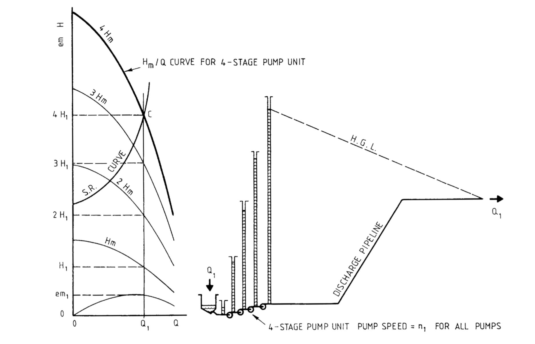
Figure A7-3 represents an arrangement similar to Figure A7-2, but extended to represent a 4-Stage Pump unit where the entire flow passes through all 4 identical pumps prior to entering the discharge pipeline.
If all 4 pumps are identical and are operated at the same speed, n1, and as all the pumps are handling the same flow rate, Q1, each will develop the same head, H1, at the same efficiency, em1, and each consume the same power, P1.
The total head developed by the 4-Stage Pump unit combined H1 + H1 + H1 + H1 = 4 x H1, that is, Duty Point “C” is Q1/4HI.
Accordingly, all 4 pumps will be operating under the same conditions except that the Suction Head and the Discharge Head of each successive stage will be progressively higher. Neglecting the small losses in the inter-stage piping and assuming that Hs for the 1st Stage Pump = X (metres) the individual values are:

TABLE 2 CALCULATION OF POWER AND HEAD FOR MULTI-STAGE SETS
If the Total Head Developed by each pump varies from one pump to another, due to different speeds or different effects of wear, the Total Head developed by the MultiStage Unit will be the sum of the individual total Heads Developed by each of the pumps.
Similarly, the Total Power Consumed will be the sum of the individual powers consumed by each of the pumps.
 FIGURE A7-3 FOUR-STAGE PUMP UNIT
 sales@mineco.vn

